
Creating Z-Wave devices
Related article: Getting Started with Z-Wave Development (500 Series) (2020-01-18)
This text gives an overview of what it means to build a Z-Wave slave device based on the 500 Series chips without a separate host MCU, i.e. writing code that runs directly on the Z-Wave chip.
Summary
5th generation Z-Wave chips have a modified 8051 core and offer a good selection of peripherals. Currently, all chips are manufactured by Silicon Labs and are available in three variants to accomodate the RF regulations of different countries. Z-Wave products must only be built with official Z-Wave chips and must be certified by a test house prior to market launch.
When building applications that run directly on the Z-Wave chip, one is expected to use KEIL C51 to compile and link the code, since the precompiled libraries required for accessing the network are compiled with KEIL as well. Furthermore, it is recommended to start one’s application by building on top of an existing example application. Unforuntately, the chips have no dedicated debugging interface, so one has to use e.g. UART or debug/test the hardware independent code in a different environment.
Z-Wave device development requires a substantial amount of money for tools, membership fees, and certification as well as time to learn the technology. On the plus side, you get access to the Z-Wave ecosystem containing thousands of interoperable devices as well as some other benefits. Evaluate whether this investment makes sense for you. Talk to a Z-Wave FAE if you are unsure.
Have a look at the glossary at the end of this blog post, in case you are wondering what an acronym stands for.
All images are provided by courtesy of Sigma Designs and Z-Wave.me.
Please note: This is an authorized translation of a Russian article titled “Как делаются Z-Wave устройства”. The original article was published via habr by Сергей Полторак on January 8, 2016. Сергей founded the Russian division of Z-Wave.me in 2009.
I originally read the English translation “As device Z-Wave become” published via Geek Magazine. However, at the beginning of 2019, Geek Magazine’s domain went offline, leaving only the Wayback Machine to still read and discover the translation.
I decided to publish another English translation to improve the odds for all non-Russian readers to benefit from the article’s breadth and unique focus on practical knowledge. Since I don’t speak Russian, I am using the original English translation and DeepL Translate to write this text.
By the way: On Dec 18, 2017, Sigma Designs was acquired by Silicon Labs.
Warning: The Z-Wave specification, hardware, and processes changed a bit since the original post was written in January 2016. See the Silicon Labs website for the latest information, e.g. the specification and document search. You might also be interested in the catalog of certified Z-Wave products.
Introduction
In this article we will explain how Z-Wave devices are created. The circuit engineering and programming of Z-Wave devices is quite similar to devices based on Arduino, AVR, or PIC. However, there are of course differences and this article will cover them.
Since I already wrote about the Z-Wave protocol, I will not cover any protocol details and instead focus more on the hardware aspects. This article will only cover the 5th generation chips and modules that were released more than two years ago.
Hardware
5th generation Z-Wave chips and modules have a modified 8051 core which is manufactured as a SoC with the following periphery:
- 128 KB of flash memory for your code
- 16 KB of XRAM and 256 bytes of IRAM which includes the SFRs
- 256 bytes of NVR, e.g. calibration data of the crystal and lock bit
- 30 GPIOs
- 2 UARTs
- 2 SPIs (master and master/slave)
- 1 USB (serial only)
- 4 ADCs 12/8 bit
- 1 scanner for 88 keys (with the ability to function while in deep sleep mode)
- 1 TRIAC controller generator with ZEROX detector
- 5 PWMs with 16 bit resolution
- 4 IR controllers and 1 IR decoder
- Loader (enabled by RESET pin or from the code by writing to the appropriate SFR register) for flashing via SPI or UART, as well as the ability to reprogram itself. Overwriting of flash memory is used for OTA firmware updates.
- Crypto acceleration for 128 bit AES encryption
- Power monitor (to monitor the battery’s charge)
The chip can be supplied with 2.3 V to 3.6 V. It consumes about 15 mA during normal operation, 35 mA while receiving, and 45 mA while transmitting. While in deep sleep mode it consumes 1 μA and can be awoken via INT1. It can also be awoken via the WUT in which case it consumes additional 0.7 μA with the WUT enabled.
Since multiple functions are available for each pin, they cannot all be used at the same time.
The abundance of functions in one chip allows you to significantly reduce the cost of the device, because you do not have to use additional microcontrollers. For example, a dimmer, door lock, battery key fob, composite sensor (temperature, humidity, …) can be made directly with the Z-Wave controller with the appropriate electrical support circuits.
Most important of all, the chip has a radio transceiver built into it. However, the transceiver is only accessible via the Sigma Designs libraries (see below). While this keeps many aspects of the hardware hidden from us, we of course know its RF characterstics:
- –104 dBm at the Z-Wave operating frequency
- 5 dBm output power
- 850 to 940 MHz operating range
We are confident that it is capable of a larger frequency range but no public description of the RF part is available and hence no way of knowing about any other scenarios in which the radio transceiver might be used. Obviously, it’s a typical SDR chip for which Sigma Designs did not reinvent the wheel.
Suppliers
The chips’ IP is owned by Sigma Designs and licensed to Japanese company Mitsumi. The 5th generation of chips is currently being produced.
A very important aspect in the development of Z-Wave is backward compatibility. This is not only true for the software level but also with regard to the chip’s form factor and chip characteristics. The current generation of modules is pin-to-pin compatible with all previous generations. The allows you to quickly upgrade your existing devices without changing the circuitry or rebooting the boards.
Chip variants
Z-Wave chips are available in two versions:
The following SiP modules are available as well. They include a quartz and need minimal setup for the chip to function:
- ZM5101, 56-QFN 8x8 mm, compatible with ZM4101 (4th generation)
- ZM5202, PCB 12.5x13.6 mm, based on SD3502, compatible with ZM3102 (3rd generation)
- ZM5304, PCB 27x15.2 mm, based on SD3503, includes EEPROM memory, SAW filter, spiral antenna, and protective cover (for “modems”, i.e. for Z-Wave controllers)
And the Mitsumi series:
- WML-C84, 56-QFN 8x8 mm, drop-in replacement for the ZM5101
- WML-C85, 56-QFN 8x8 mm, in comparision to C84 it has an integrated SAW filter
- WML-C86, 56-QFN 15x15 mm, integrated SAW filter and EEPROM, increased TX power and RX sensitivity, protective cover
- WML-C87, 56-QFN 15x15 mm, integrated SAW filter and EEPROM, increased sensitivity RX, protective cover
Each module provides a different subset of functionality compared to the “full” version of the SD3502.
The modules with integrated SAW filter are available in three versions for three different world regions and differ in the supported frequency range:
- EU/RU/CN/MY/UAE/IN
- US/IL
- ANZ/BR/JP/TW/HK/KR
Many of these modules can be purchased via DigiKey but Sigma Designs sells chips in large volumes only after prior arrangement.
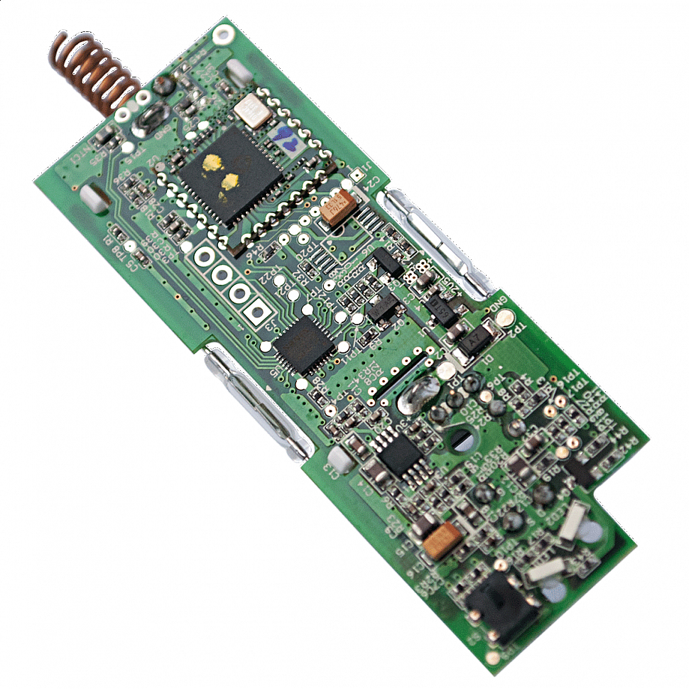
Some manufacturers decided to make their own modules. For example, Philio Tech manufactures the MD003 (drop-in replacement for the ZM5304 based on SD3503, but without antenna), MD006 (based on SD3503), and MD008 (something in between ZM5101 and ZM5202 based on SD3502). The first picture at the beginning of this article shows the Philio PST-02 which is based on MD008.
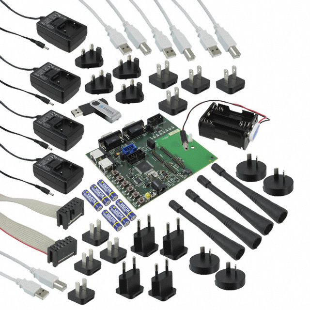
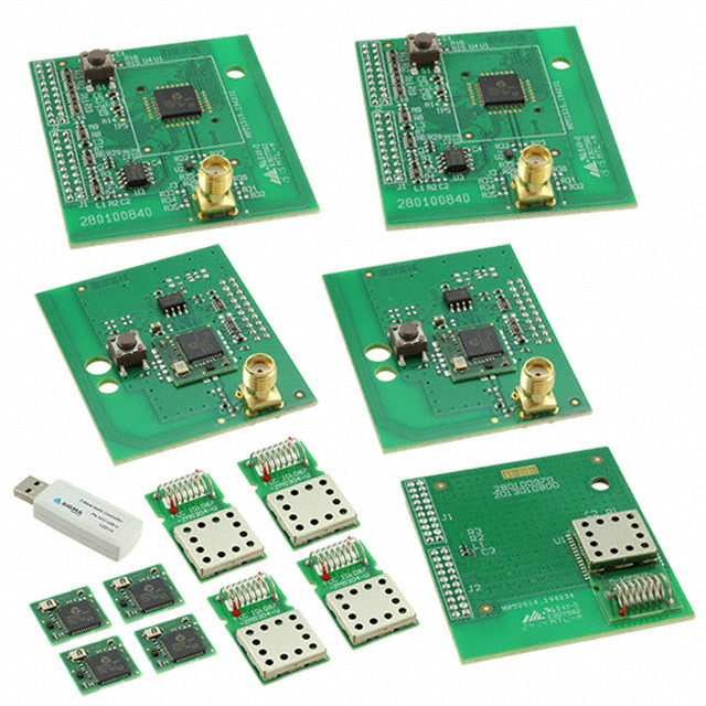
DevKit
Sigma Designs also offers a developer kit:
- A set of chips of different form factors, including those on developer boards, which are installed directly on the programmer (very convenient for prototyping)
- Sniffer (for capturing Z-Wave frames—useful for debugging)
- USB stick to run the controller
- Several sensors and actuators
- Windows based software for programmer, sniffer, and controller as well as supporting tools
- Z-Wave SDK for creating firmware for Z-Wave chips (see below)
- All sorts of wires and power supplies
- Programmer ZDP03A
Z-Wave chips use a custom protocol for programming and therefore require special programmers. Currently, there are three options:
- The above mentioned programmer ZDP03A provided by Sigma Designs as part of the DevKit. It is only recommended for development but not production use.
- A programmer more suitable for production is provided by us, Z-Wave.Me.
- A variety of rugged programmers for production use are offered by Equinox.
The DevKit consists of two parts: a generic one for all world regions and a regional one for your specific world region respectively allowed frequency range.
A DevKit costs between $1500 to $3500 depending on the number of developer boards and programmers as well as the presence or absence of sensors/actuators.
Legal considerations
Patents, licenses, and NDAs do not allow the use of Z-Wave chips and modules for other purposes than Z-Wave. Also, Z-Wave devices must not be created on a non-Z-Wave chip. This allows Sigma Designs to include the license fees (paying for protocol development, software, utilities, marketing) as part of the cost of chips and modules.
In order to call your device Z-Wave compatible, you need to pass the certification (see below).
According to the license agreement, each Z-Wave device has to have the Z-Wave logo somwhere on it—usually on the back. This promotes Z-Wave as a brand.
![]()
Typical electrical setup
Let’s get back to the hardware. The following image showas a typical ZM5101 connection diagram:
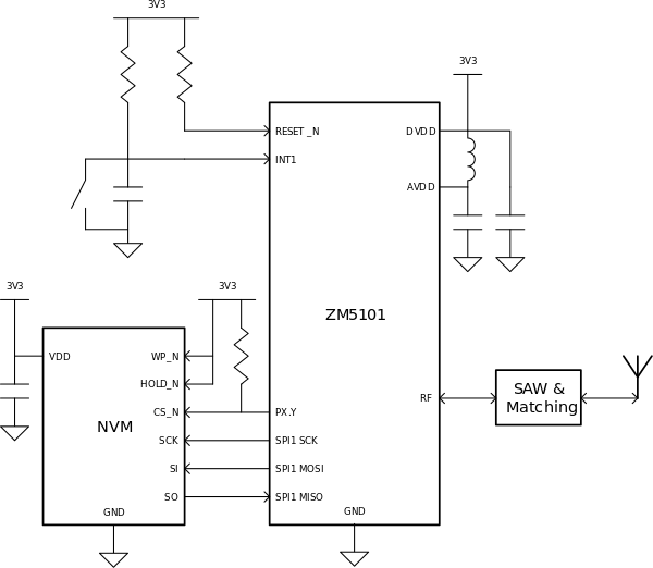
The NVM is SPI EEPROM or flash memory of at least 16 KB. It is necessary for storing data about network nodes, routes, and so on. It is possible to create devices without an external EEPROM by using a flash memory block and thereby reducing the available code space. External EEPROM memory takes up one of the SPIs and one additional GPIO pin for CS. SPI pins can easily be used as GPIO or to connect another SPI Slave while CS is raised to 3.3 V. The same SPI is used to program the Z-Wave chip when RESET is pulled down. That’s why we need a CS pull-up (ZM5101 becomes SPI Slave, and the second Slave is obviously not needed here).
We are free to use all remaining pins for whatever we want the device to do.
Let’s say we want to create a complex device:
- A contact sensor
- A light sensor (photoresistor)
- A beautifully flashing three color LED
- 3 relays
For the relays we are going to use a darlington ULN2003, since the current limit of 20 mA from the ZM5101’s pins is not enough for an electromagnetic relay and it will supply the relay via 5 V or 12 V.
All of this can be immediately connected to the Z-Wave chip:
- Dry contact sensor via
INT0(P1.0),INT1(P1.1), or any other GPIO pin if it is okay for you to simply poll the GPIO instead of using an ISR handler - A light sensor as part of a voltage divider via
ADC0or P3.4. - A three color LED via
PWM0,PWM1, andPWM2(P0.4 to P0.6). This allows you to make smooth color transitions. - 3 relay inputs via GPIOs, e.g. P2.0, P2.1, and P2.5. P2.2 to P2.4 occupy the EEPROM connected via SPI.
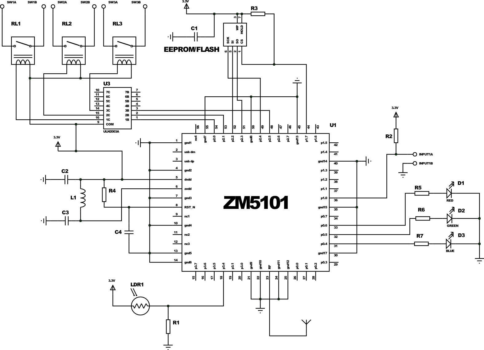
Even after connecting all these components, we still have 18 pins left. In comparison, with the 3rd generation of Z-Wave chips and modules (ZM3202) we wouldn’t even have been able to connect the above components.
Firmware
Like other 8051 chips, Z-Wave chips organize their GPIO pins in 4 ports. One SFR controls the direction (input/output), one the pull-up for GPIOs configured as inputs, and one is used for reading/writing the value.
Timer, UART, SPI, and other functions are similar to other 8051 chips: TMOD/THx/TLx, UARTCON/UARTBUF/UARTSTAT, SPIxCON/SPIxDATA/SPISTAT, and so on.
There are so many registers that in the 5th generation of chips one has to enter the SFRPAGE register to switch between SFR mapping pages and IRAM. The size of 128 KB flash memory also required the use of memory banks, which significantly complicates the translated code, filling it with many transfers from bank to bank via COMMON bank.
In theory, any compiler, such as SDCC (GPL), can be used to compile code for the Z-Wave chips. However, there is no documentation on all these ports, registers, internal memory mapping and so on. Instead of making this information public, Sigma Designs chose to supply pre-compiled libraries that provide a convinient API to access the chip’s hardware (wrappers for SFR access) and for accessing the Z-Wave network, i.e. sending commands to other nodes, managing the network, updating routes and more. Due to memory size constraints Sigma Designs provides libraries for different device classes, e.g. controllers, slaves, and gateways. These libraries are built for a specific version of KEIL.
The libraries implement the following lower levels of the Z-Wave protocol:
- PHY: Directly coding and decoding at the desired frequency, choice of transmission channel, LBT
- MAC: Error control, addressing within the area of visibility
- Transport: Confirmation, repetition
- Network: Routing, retransmission, route updates, search for new routes, inclusion in the network, removal from the network
Sigma Designs ensures the compatibility of all devices for these levels and is driving protocol development. The big advantage of this approach is that one cannot screw up these lower levels and has a simple high-level API to access the network. Furthermore, Sigma Designs takes care of fixing any defects that are discovered in these levels.
In order to interact with the network, developers rely on a simple API to communicate with other nodes. However, the specification also requires strict compatibility at the higher levels: session, presentation, and application. Interactions at these levels are in the hands of application developers.
The library allows node A to send a command to node B. The command must adhere to a specific message format defined in the specification (see Command Class Specification, about 900 pages). This will allow node B to properly decode the command and perform the corresponding action on the periphery.
Z-Wave libraries make heavy use of callbacks. The main logic is in the library and control is only transferred to the user code at certain times:
- At startup.
Two points of entry: (1) Right after the start of the chip for hardware initialization and (2) later, when the library was initialized and you can already use some of its functionality—comparable tosetup()used by Arduino. - When the library is not busy,
i.e. receiving/sending data, forwarding packets of other network nodes, responding to a controller’s requests. Here you can poll the buttons, access the ADC and so on—comparable toloop()used by Arduino. - When a command is received by us.
All time consuming and asynchronous functions can also be passed on to the callback. For example, when you call the packet sending function, you can specify the handler that will receive the sending status (delivered, not delivered, and the error code). In the same way, the timer subsystem is executed (besides the exact timers based on TIMER and GPT): it is possible to start up to 5 software timers that work with 10 ms increments (TIMER0 cannot be used since it is already used by the library, among other things to implement the software timers). All this makes it easier for the programmers of the final device manufacturer.
Z-Wave libraries also come with a huge number of specification compliant data structures and constants predefined in the header files greatly simplifying development.
Sigma Designs also provides two dozen examples of simple device applications, such as a relay, binary sensor, or door lock, with the minimum functionality required to operate and qualify as Z-Wave Plus. Funnily enough, more than half of the Z-wave devices in the field use these examples without a single modified line, except for the ManufacturerId, ProductId, and ProductTypeId. These identifiers must be unique for each manufacturer and device and are therefore changed prior to device certification. If it were not for the certification, they would probably not be changed.
All header files, libraries, and sample code is available as part of the Z-Wave SDK a.k.a. ZDK. The ZDK is distributed under the NDA. You usually have to sign the NDA once you purchase a DevKit.
As mentioned earlier, KEIL C51 is required to develop applications that run on the Z-Wave chip, e.g. ZM5202. It costs about 2600 € but this is not all we have to spend—there are a couple more things we will come to later.
Command Classes and the NIF
In addition to programming the logic of working with peripherals, it is necessary to declare the list of supported Command Classes of the device being created in the NIF, as well as to implement the declared Command Classes (read more about Command Classes in this article). In fact, it comes down to writing code that processes all the possible commands of all the supported classes.
For example, for the Switch Binary Command Class (ID 0x25) you need to process the Set Command (0x25 0x01) by turning on a relay or LED, the Get Command (0x25 0x02) by replying with the Report Command (0x25 0x03 0xXX) where 0xXX is either 0x00 or 0xFF, depending on the current state of the relay or LED.
For our example of a “complicated” device (see above), it will look something like this in pseudo-code:
switch (pCmd[0]) {
  case COMMAND_CLASS_MULTI_CHANNEL:
    switch (pCmd[1]) {
      case MULTI_CHANNEL_CMD_ENCAP:
        switch (pCmd[4]) {
          case COMMAND_CLASS_MULTI_SWITCH_BINARY:
            // check the channel number
            if (pCmd[3] == 1) {
              switch(pCmd[5]) {
                case SWITCH_BINARY_SET:
                  pin_set(P2_0, pCmd[6] ? 1 : 0);
                  break;
                case SWITCH_BINARY_GET:
                  // parameters: who sent the request; channel of the remote node; our channel; Command Class, Command; data
                  SendMultiChannelReport(srcNodeId, pCmd[2], pCmd[3], COMMAND_CLASS_MULTI_SWITCH_BINARY, SWITCH_BINARY_REPORT, pin_get(P2_0));
                  break;
              }
            }
            if (pCmd[3] == 2) {
              switch(pCmd[5]) {
                case SWITCH_BINARY_SET:
                  pin_set(P2_1, pCmd[6] ? 1 : 0);
                  break;
                case SWITCH_BINARY_GET:
                  SendMultiChannelReport(srcNodeId, pCmd[2], pCmd[3], COMMAND_CLASS_MULTI_SWITCH_BINARY, SWITCH_BINARY_REPORT, pin_get(P2_1));
                  break;
              }
            }
            if (pCmd[3] == 3) {
              switch(pCmd[5]) {
                case SWITCH_BINARY_SET:
                  pin_set(P2_5, pCmd[6] ? 1 : 0);
                  break;
                case SWITCH_BINARY_GET:
                  SendMultiChannelReport(srcNodeId, pCmd[2], pCmd[3], COMMAND_CLASS_MULTI_SWITCH_BINARY, SWITCH_BINARY_REPORT, pin_get(P2_5));
                  break;
              }
            }
            break;
          case COMMAND_CLASS_MULTI_SENSOR_BINARY:
            if (pCmd[3] == 4) {
              switch(pCmd[5]) {
                case SENSOR_BINARY_GET:
                  SendMultiChannelReport(srcNodeId, pCmd[2], pCmd[3], COMMAND_CLASS_MULTI_SENSOR_BINARY, SENSOR_BINARY_REPORT, SENSOR_BINARY_TYPE_GENERAL_PURPOSE /* датчик общего назначения */, pin_get(P1_0));
                  break;
              }
            }
          case COMMAND_CLASS_MULTI_SENSOR_MULTILEVEL:
            if (pCmd[3] == 5) {
              switch(pCmd[5]) {
                case SENSOR_MULTILEVEL_GET:
                  SendMultiChannelReport(srcNodeId, pCmd[2], pCmd[3], COMMAND_CLASS_MULTI_SENSOR_MULTILEVEL, SENSOR_MULTILEVEL_REPORT, SENSOR_MULTILEVEL_TYPE_LUMINESENCE /* освещённость */, 0 /* целое в % */, analog_get(P3_4));
                  break;
              }
            }
          case COMMAND_CLASS_MULTI_SWITCH_MULTILEVEL:
            if (pCmd[3] == 6) {
              switch(pCmd[5]) {
                case SWITCH_MULTILEVEL_SET:
                  pwm_set(P0_4, pCmd[6] > 99? 99 : pCmd[6]);
                  break;
                case SWITCH_MULTILEVEL_GET:
                  SendMultiChannelReport(srcNodeId, pCmd[2], pCmd[3], COMMAND_CLASS_MULTI_SWITCH_MULTILEVEL, SWITCH_MULTILEVEL_REPORT, pwm_current(P0_4));
                  break;
              }
            }
          case COMMAND_CLASS_MULTI_SWITCH_MULTILEVEL:
            if (pCmd[3] == 7) {
              switch(pCmd[5]) {
                case SWITCH_MULTILEVEL_SET:
                  pwm_set(P0_5, pCmd[6] > 99? 99 : pCmd[6]);
                  break;
                case SWITCH_MULTILEVEL_GET:
                  SendMultiChannelReport(srcNodeId, pCmd[2], pCmd[3], COMMAND_CLASS_MULTI_SWITCH_MULTILEVEL, SWITCH_MULTILEVEL_REPORT, pwm_current(P0_5));
                  break;
              }
            }
          case COMMAND_CLASS_MULTI_SWITCH_MULTILEVEL:
            if (pCmd[3] == 8) {
              switch(pCmd[5]) {
                case SWITCH_MULTILEVEL_SET:
                  pwm_set(P0_6, pCmd[6] > 99? 99 : pCmd[6]);
                  break;
                case SWITCH_MULTILEVEL_GET:
                  SendMultiChannelReport(srcNodeId, pCmd[2], pCmd[3], COMMAND_CLASS_MULTI_SWITCH_MULTILEVEL, SWITCH_MULTILEVEL_REPORT, pwm_current(P0_6));
                  break;
              }
            }
            break;
        }
    }
}
The NIF will contain the following:
0x25: Switch Binary CC0x26: Switch Multilevel CC0x30: Sensor Binary CC0x31: Sensor Multilevel CC0x60: Multi Channel CC- and ten other Command Classes required for network management.
This code is simplified but the overal logic is the same. Further information can be found here.
Obviously, all devices must handle the commands in more or less the same way. Three years ago, we created a common code base for our devices. Many of our devices differ only in one .h file. More complex ones have a couple more files for special functionality.
Certification
After you have came up with the idea for the device, made a prototype, and wrote the firmware for it, you need to certify it. Certification is required by Sigma Designs to ensure your device’s compliance with the Z-Wave specification. The certification process consists of two parts: Technical Certification and Market Certification. Market Certification verifies the end user documentation (using key Z-Wave terminology) as well as the presence and correct use of the Z-Wave classic respectively Z-Wave Plus logo.
Z-Wave certification is carried out by one of three test houses: Pepper One in Germany, BuLogics in USA, or Sigma Designs in Denmark. Prior to certification, you need to perform all tests yourself—this is called Self-Certification. It allows you to detect and eliminate many errors ahead of the costly certification and increase your chances for passing. Sigma Designs provides a Compliance Test Tool (CTT) to all full Z-wave Alliance members for this purpose. All development tools are also used by the test houses themselfes.
It also exists a certification form that defines which exact tests have to be performed. Depending on your device’s capabilities, it may range from 100 to 300 different tests. Every test is accompanied by detailed test instructions.
The entire process is very transparent. It is clear in advance what and how your device will be tested—this is, if you read the available documentation ;)
Certification is a time consuming and dreadful process. Certification also costs money: depending on the complexity of the DUT it can cost from $3000 to $5500. If the number of issues found during the certification stays reasonably low, you are allowed to fix them within a month—the so called ad-hoc period. If you had too many issues, you have to fix them and reapply for certification which includes paying the certification fee for a second time. This is a good incentive for testing your devices well. We have done this only once and—honestly—it did make us feel bad about ourselves.
Significant changes in device functionality or behavior with regard to the Z-Wave network requires re-certification at half the price of the initial certification. Often a device is sold in different versions, e.g. colors, logos, GUI changes, without any significant changes with regard to the Z-Wave network. In those cases, it suffices to repeat the Market Certification free of charge.
Referring again to our “complex” device, the CTT will detect that we do not handle the StartLevelchange and StopLeveLChange commands required for dimming as part of the Switch Multilevel Command Class. If we did not fix this and try to certify the device, it would not pass. We did not include the necessary code in the above code snippet, since it is not necessary to get accross the general idea.
Please remember that you can only apply to the certification and use the CTT if you are a full or principal member of the Z-Wave Alliance—it is not enough to be an Affiliate Member. For this privilege you have to pay another $4000 per year.
Debugging
I’d like to mention right away that there is no JTAG or other debugging interfaces in the Z-Wave chips! This makes the debugging process quite terrible and nearly unbearable. Therefore, it is not uncommon for complex code to be tested and debugged first on a 8051 chip from, e.g. Silicon Labs, that has a JTAG or C2 interface and can be easily used with the KEIL debugger.
We also test parts of the code by building it on Linux using gcc and running various tests, e.g. we test our queue for communicating with other nodes. Unfortunately, this does not allow us to catch any overflow errors that would be triggered by microcontroller specific properties (for example, reduced stack size, lack of registers for recursive or simply deeply nested function calls). It also does not allow us to debug the code related to the SFRs or other chip specific hardware. Anyway, all platform independent defects are easily detected. We often have to use assembly (d52 is all we have!) as well as KEIL’s convenient tools for working with map files.
Otherwise, we have to settle for debugging via I2C, SPI, or UART. This works for simple problems where the stack or other memory is not corrupted by other parts of the code.
Another challenge is the creation of battery devices. In order to reduce power consumption, you need well thought through code that takes into account the time it takes operations to finish (ADC, radio transmissions, EEPROM access) and the location of variables—256 bytes of XRAM are powered even in deep sleep mode, allowing you to not read the slow EEPROM and instead to quickly make a decision and stay in sleep mode longer.
Complex devices
When creating complex devices that require many pins, it may be necessary to use multiple chips that communicate with each other using UART, SPI, or I2C. In such cases, part or all of the communication with external components is done by a second more advanced chip a.k.a. the host MCU which uses the Z-Wave chip as a “modem” to access the Z-Wave network. It is very convenient to use more advanced Atmel or ARM Cortex-M chips since they have better peripherals and consume less power (nA instead of μA).
Z-Wave Serial API
There is an alternative to running the application directly on the Z-Wave chip: running it on another MCU a.k.a. host MCU and letting both chips communicate via UART or SPI using the so called Serial API, a Z-Wave specific protocol developed by Sigma Designs. This approach is usually followed for more complex devices that need a dedicated application processor as well as for multi purpose computers like the Raspberry Pi and of course desktop PCs. By and large the Serial API provides the same API access as if the code were running directly on the Z-Wave chip.
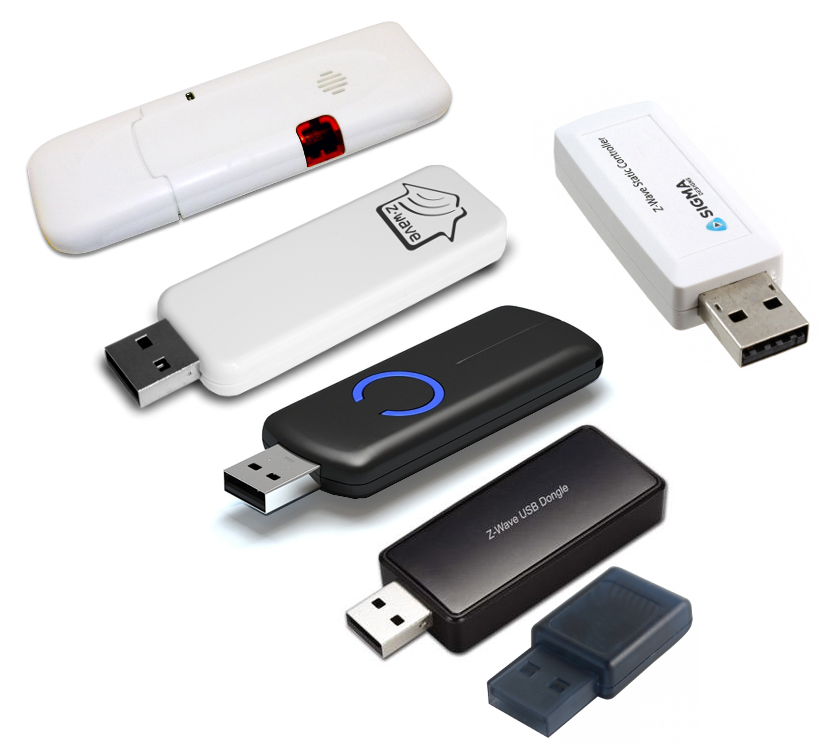
This separation allowed third parties to create a market for Z-Wave USB sticks that is separate from the market of software for them: many manufacturers offer interchangeable USB sticks, while software manufacturers create software that works with any of those USB sticks. An example of such a software is the PC Controller that is part of the ZDK.
This approach makes it easier for manufacturers to lauch Z-Wave enabled products: a manufacturer of TV set-top boxes or routers can create a solution based on a third-party Z-Wave USB stick. Once the number of sales increase the manufacturer may decide to replace the Z-Wave USB stick with a Z-Wave module to reduce the costs (among other things). In these cases most choose the ZM5304.
Still, some companies that manufacture both hardware and software prefer to use our USB sticks so they don’t have to worry about any Z-Wave details and just have to sell their software. We eliminate many problems that exist in code from Sigma Designs and supplement it with our own extensions. Others, e.g. Merten, have replaced the Serial API with their own protocol.
Training and support
Each region has several Sigma Designs FAEs assigned to it. They help new manufacturers to get started with Z-Wave, receive bug reports, and help clear up issues during the certification process.
The Z-Wave Alliance also actively supports manufacturers. Beyond offering testing tools and training materials it organizes the UnPlug Fest conference several times a year in different parts of the world. It allows developers to share experiences and test their devices with those of other participants. Sigma Designs FAEs also participate in these events. UnPlug Fest is always accompanied by a two-day training for new developers.
Furthermore, the Z-Wave Alliance organizes the Interoperability Lab in New Jersey, USA. There you can test your devices both for compatibility with other devices on a protocol level as well as on the RF level in a special RF laboratory.
In addition to the above, the Z-Wave Alliance has working groups that work on the improvement of the Z-Wave protocol. All developers can offer their ideas and influence the functionality of the next version of all Command Classes as well as the protocol overall.
For more information, visit the Z-Wave Alliance website.
A little more on money
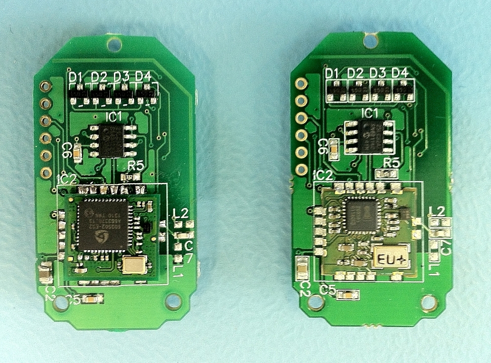
Let’s do a rough estimation of how much it will cost us to build a simple keychain device. The device on the left uses a 5th generation module and the one on the right a 3rd generation module.
I am assuming that for the first series we are going to produce 5,000 units. Each unit’s price will depend on the BOM and development costs (software, marketing, sales, etc.).
Hardware
A rough estimation yields that the components (excluding the Z-Wave module), PCB, and assembly will cost about $7. This may seem expensive but remember, that we are only producing only a couple thousand units instead of millions. The ZM5202 costs another $5 (alternatives cost about $2 which leaves $3 for the Z-Wave license). Another $1 for the housing (thanks to Alibaba). This results in a total of $13.
Firmware
Firmware development costs consist of the following items:
- $2600 KEIL C51 license
- $2500 Z-Wave DevKit (ZDK)
- $4000 Z-Wave Alliance membership for a year
- $3500 Certification
This results in about $2.5 per unit. Once additional variants will be produced within the same year of the first batch, the first three items will be distributed across all units—only the certification has to be repeated for each variant that is a significant change with regard to the Z-Wave network when compared to all other variants that were already certified.
Of course, we also have to factor in the time required for programming the firmware. In our experience, it will take at least 10 man-months until you have a simple fully certified device. This translates to $2 to $4 for the first device. For all following device developments you will benefit from the already existing experience and be able to cut your time investment to a half or a third of the original investment.
Everything else
Now we are at $19.5 for 5,000 units of a simple device. Once we add VAT, transport, import tax, RF certification, a margin for ourselves and sales partners in the channel, and a minimum of marketing we arrive at about $60. Judging from experience how the production volume will grow, this figure will be closer to $15 which translates to $45 in retail.
Closing thoughts
The first prototype batch will cost at least $20,000. There is no way that anyone new to this can make it with less money.
Is it possible to reduce costs by using a proprietary wireless communication protocol and another chip from Texas Instruments or Silicon Labs? Sure, but the big advantage of Z-Wave is the ecosystem your device becomes part of. Customers will be interested in buying your device not solely because of your device’s functionality but because it allows them to build a solution of which your device is just one of many. It is true that using Z-Wave will cost you 20% to 30% more, but it is often justified.
The moral of the story
Creating your own Z-Wave device is pretty much like creating any other device and can therefore be accomplished by any company familiar with microcontrollers and ideally RF designs. Thanks to the SoCs, many types of devices can be developed directly on the Z-Wave chip without the need for an additional host MCU and with few additional components. However, you are required to read the about 2,000 pages of protocol specification and pass the certification.
So, is Z-Wave worth the trouble? Do you really need to build a Z-Wave device? If you only want to create a remotely controlled light bulb, a motion sensor or something even simpler, Z-Wave will probably only be a burden to you. However, if you want to create a device that can be integrated into a smart home and seamlessly interact with a whole ecosystem of existing devices, then Z-Wave is the right choice. After all, usually only larger companies are able to produce 30 to 50 different devices that can be used together to create a modern smart home, e.g. keyrings, relays, thermostats, and door locks. By building a Z-Wave device, you can increase the interest in your device by making it part of an existing smart home ecosystem.
Somehow difficult for the simple geek (advertisement)
As a developer, do you dislike the idea of having to pay a lot of money and having to understand the Z-Wave protocol but you are also not satisfied with available devices? Then you might be interested in one of our new devices called Z-Uno.
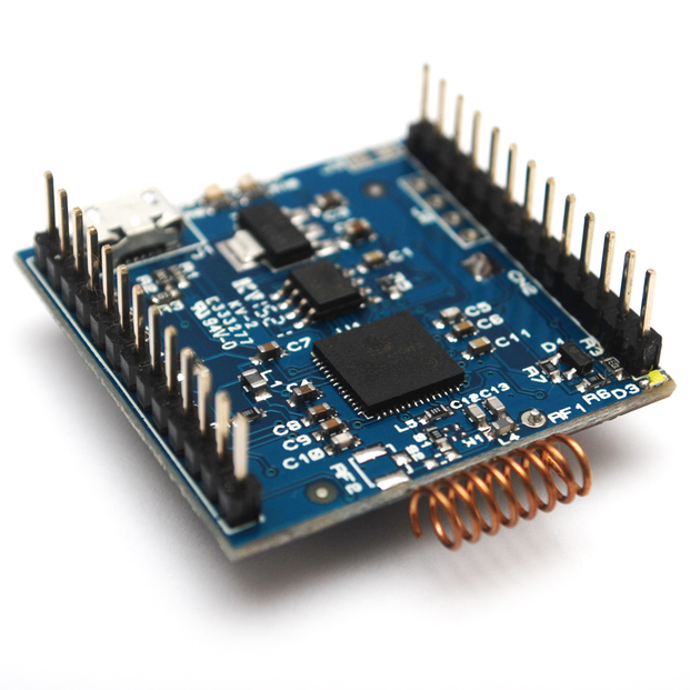
In short, it is a small board based on the ZM5101. Almost all its pins are accessible to you. You can use the Arduino IDE to write code and load it into the Z-Uno. We wrote our own Arduino library allowing you to describe your device’s Z-Wave functionality (up to 10 functions) and define all required callbacks. This makes Z-Uno an Arduino clone with a 8051 at its core and built-in support for Z-Wave. See the Z-Uno product page for more information.
Glossary
- ADC: Analog to Digital Converter
- AES: Advanced Encryption Standard (aka Rijndael)
- API: Application Programming Interface
- BOM: Bill of Materials
- CC: Command Class
- CPU: Central Processing Unit
- CS: Chip Select
- CTT: Compliance Test Tool
- DUT: Device Under Test
- EEPROM: Electrically Erasable Programmable Read Only Memory
- FAE: Field Application Engineer
- GPIO: General Purpose Input Output
- IR: Infra Red
- JTAG: Joint Test Action Group
- LBT: Listen Before Talk
- LED: Light Emitting Diode
- MCU: Microcontroller Unit
- NIF: Node Information Frame
- NVR: Non-Volatile Registers
- OSI: Open Systems Interconnection
- PC: Personal Computer
- PCB: Printed Circuit Board
- PWM: Pulse Width Modulation
- QFN: Quad Flat No-leads (package)
- RAM: Random Access Memory
- RF: Radio Frequency
- RX: Receive
- SAW: Surface Acoustic Wave
- SDK: Software Development Kit
- SDR: Sofware Defined Radio
- SFR: Special Function Register
- SoC: System on a Chip
- SPI: Serial Peripheral Interface
- TRIAC: TRiode for Alternating Current”
- TX: Transmit
- UART: Universal Asynchronous Receiver/Transmitter
- USB: Universal Serial Bus
- WUT: Wake Up Timer
- ZDK: Z-Wave SDK
- ZEROX: Zero Cross